thyristordiagnose_en.pdf I DT LD CS 26 May 2011
SIEMENS
Question:
How can I perform a thyristor diagnosis?
Answer:
Measurement of the resistance of the power semiconductors
The resistance of the power semiconductors can be measured via the power terminals: input
and output. Please refer to the wiring diagrams of the power section in the Operating
Instructions.
Note: Before measuring the resistance, the following precautions must be taken:
1) Disconnection of the line supply voltage to the power section
2) Check for zero potential at input and output directly on the power section of the power
converter
3) Disconnect load terminal at output of the power converter
When measuring the power semiconductors, please note that these are connected by means
of an RC element (RC circuit). The capacity C of the circuit must first be charged via the
voltage source of the ohmmeter (or recharged when reversing polarity of the ohmmeter),
therefore giving a low-resistance reading for a certain initial period before the indicator shows
the actual high-resistance value. This resultant charging process is also a sign that the RC
circuit is in order, enabling the occurrence of this effect to be used additionally for checking
the RC circuit.
The diode:

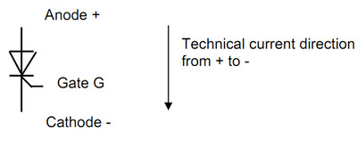
The thyristor:

Measurement at the diode:
Perform using the "diode" measurement range; the voltage drop at the diode of approx. 0.5 V
is shown in the forward direction. Anode diode connected with positive terminal, cathode
diode connected with negative terminal of the measuring instrument: Diode in forward
direction, means approx. 0.5 V voltage drop in the case of 1 diode.
Measured with polarity reversal of the measuring instrument, it produces a high-resistance
measurement; high-resistance measurement result (setpoint > 100 kOhm).
Measurement at thyristor, between anode and cathode: for both polarities of the ohmmeter,
high-resistance measurement result: setpoint > 100 kOhm.
If available, check the blocking strength of the thyristor using an insulation tester (<1000 V).
The impedance should be > 100 kOhm.
Measurement at the gate of the thyristor:
Gate G connected with positive terminal of the ohmmeter and cathode with the negative
terminal in forward direction and then with polarity reversed:
Forward direction, and non-conducting direction low-impedance result about 15 Ohm,
with "Diode" measurement range about 20 to 30 mV voltage drop (measured with a digital
measuring instrument).
The forward direction of the semiconductor, approx. 10 Ohm differs clearly from a short
circuit that produced zero Ohm.
The blocking direction differs from an open circuit with the value indefinitely; this depends on
the maximum value that can be indicated by the corresponding ohmmeter.
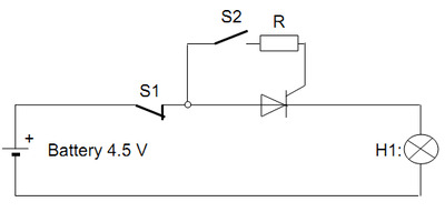
Testing of the thyristor for triggering ability - By means of the following circuit:

With a pulse from switch S2, the thyristor to be tested can be triggered.
At a higher battery voltage, limit the gate trigger current by means of resistor R to about 300 mA.
When the thyristor has triggered, lamp H1 illuminates.
If the lamp only remains lit for as long as S2 is closed, then the holding current of the thyristor of about 250 mA is not exceeded.
The thyristor can be turned off by opening switch S1 (below lower holding current limit). |


