Плата обратной связи энкодера Parker
ENCODER RECEIVER OPTION (Feedback Card) HA388867 Issue 4 Technical Manual
 
Description
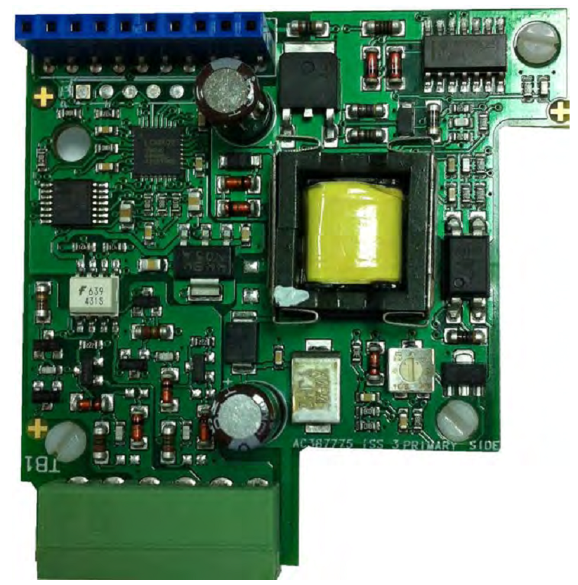
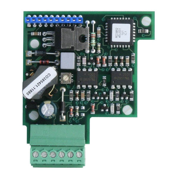
The Encoder Receiver Option allows incremental encoders to be connected directly to the motor controller to provide highly accurate speed feedback measurement. It mounts directly to the Main Control Board by means of three support stand-offs and a 10-pin interface connector built in to the board. A convenient board-mounted plug-in terminal block is provided for field connections.
590P-Encoder-Board-Manual HA388867 issue 4.pdf
Advantages
The Encoder Receiver Option board offers the following advantages:
• Contains two optically isolated differential inputs for channels A and B
• Decoding logic to interface the encoder to the control board
• Supplies fixed or customer-adjustable voltage, isolated encoder power supply
Used On
This option can be used on:
• 590 and 590P Series DC Controllers
Available Options
The Encoder Receiver is available in the following options:
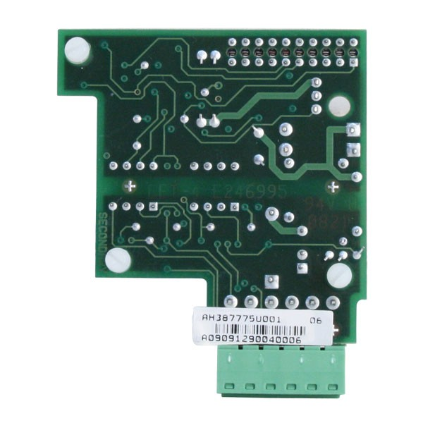
AH387775U001 Encoder Receiver Customer Calibrated
AH387775U005 5V Encoder Receiver Option PCB
AH387775U012 12V Encoder Receiver Option PCB
AH387775U015 15V Encoder Receiver Option PCB
AH387775U024 24V Encoder Receiver Option PCB
Note: An adjustment potentiometer sets the supply voltage and may be calibrated for various voltages. Refer to the Application Notes, page 6. When used with Parker SSD Drives Encoder, AH387775U015 must be used.
Specifications
Maximum Input Frequency 100kHz per channel
Receiver Input Current < 10mA per channel
Input Format Two differential channels in quadrature
Minimum Differential Input Voltage 2.5V
Maximum Differential Input Voltage 30V
Encoder Supply Capacity 2W maximum
Terminal Wire Size (maximum) 16 AWG
Terminal Tightening Torque Minimum 0.22Nm (1.9 pound-inches)
Recommended 0.4Nm (3.5 pound-inches)
590 Installation
1. Unwrap and handle the option board using correct static safety procedures.
2. Lift the lower cover of the controller door into the open and locked position.
3. Align the 10-pin connector on the option board with the controller pins on the left of the controller door board.
4. Carefully push the option board on to the pins. All three white support stand-offs should engage the controller door board.
5. Refer to the motor controller Product Manual for software selection and scaling of the feedback option
Encoder Receiver Option 590 Mounting
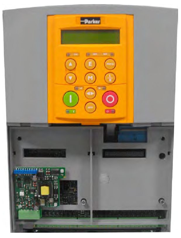
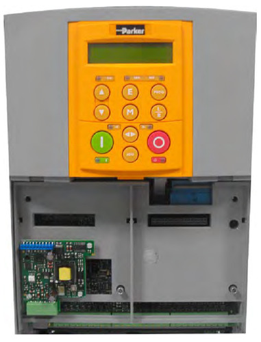
590P Installation
1. Unwrap and handle the option board using correct static safety procedures.
2. Loosen the two screws that retain the terminal cover, and remove the cover.
3. Align the 10-pin connector on the option board with the controller pins in the left-hand option bay of the controller housing.
4. Carefully push the option board onto the pins. All three white support pins should engage the controller housing.
5. Refer to the motor controller Product Manual for software selection and scaling of the feedback option.
Adjusting the Customer Calibrated Option AH387775U001
The Encoder Receiver Option can be ordered for standard supply voltages of 5, 12, 15 and 24V dc. For applications requiring different voltages, the Customer Calibrated option (AH387775U001) can be purchased and the following procedure used to adjust the output voltage setting.
1. Install the Encoder Receiver Option card on the drive. Do NOT connect it to the encoder yet.
2. Power-up the drive.
3. Measure the voltage between terminals E1 and E2. This voltage can range from 5V to 30V dc.
4. Adjust the adjustment potentiometer until the desired output voltage is reached. Turning the adjustment potentiometer clockwise increases the output voltage.
5. Connect the encoder and re-check the voltage at the encoder terminals.
Note: If the voltage drops by more than one volt, check the encoder wiring for excessive loading. Adjusting the adjustment potentiometer to compensate for an excessive line voltage drop is not recommended.
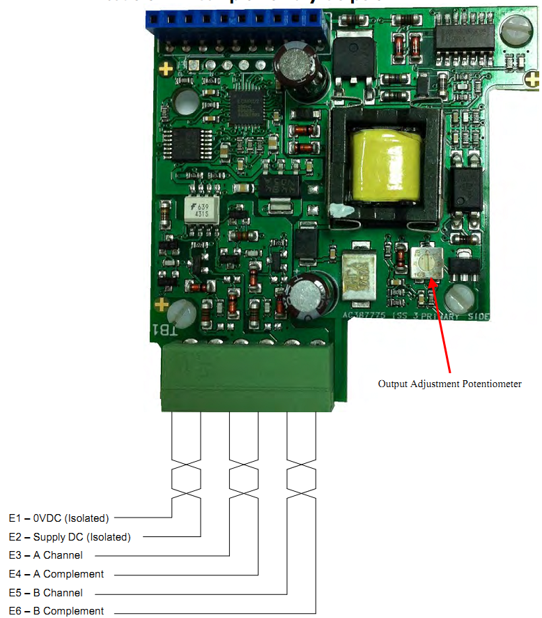
Figure 2 shows the terminal designations and the location of the adjustment potentiometer. In cases where the encoder receiver card or the motor controller cannot supply enough power for the encoder, use an external power supply. The supply should be isolated from ground, that is neither the 0V dc nor the +V dc should be connected to ground.
All wiring to the Encoder Receiver Option board should be in screened cable. Cable with an overall screen or a screen over each individual pair may be used. Connection to earth should be made at the receiver end ONLY if possible, and should be in a star configuration. Take special care wiring the encoders to the option board due to the low level of the signals.
Encoders with Complementary Outputs
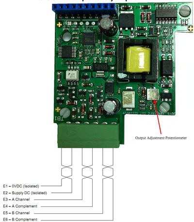
Single-Ended Encoders
Note that differential encoders are recommended due to their better noise immunity.
When using single-ended encoders:
1. Connect the A and B channels to terminals to E3 and E5 as shown above.
2. Connect terminals E4 (A complement) and E6 (B complement) to E1 (0V dc)
Recommended cable (3 pairs individually screened):
Belden equivalent 8777
Parker SSD Drives Part Number CM052666
Parker SSD Drives Encoder Connection
Function MS Connector Pin Receiver Terminal
Channel A A 3
Channel A Complement G 4
Channel B B 5
Channel B Complement H 6
Marker C
Marker Complement I
Vcc Supply D 2
Vcc Sensor (not used) E
0V F 1
0V Sensor (not used) -
Cable Screen
Recommended Encoder Litton: Parker SSD Drives Part Number:
G71SCLDBI1000-531-15EA DD385536U010 (1000 line)
Alternative Encoders Heidenhain: Avtron: ROD 534.1013 M945 1 R 1000 B C 15
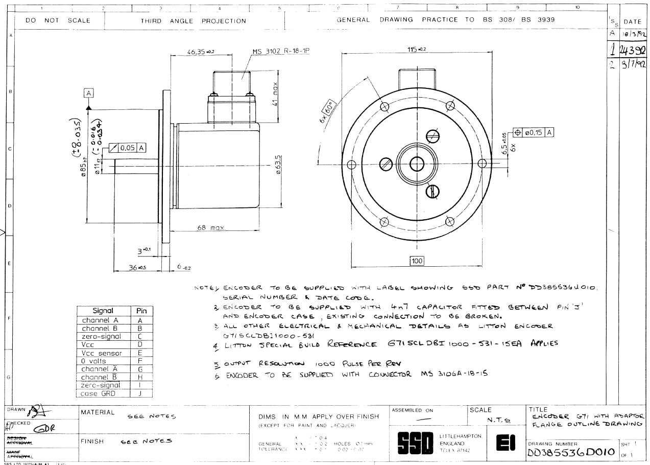
Parker SSD Drives Recommended Encoder Specification
Mechanical Specification
Dimensions Figure 2 : Outline Drawing of Encoder with
Adaptor Flange
Weight Approximately 650g
Starting Torque (25°C) 0.007Nm maximum
Slewing Speed (maximum) 6000 rpm
Shaft Loading - Axial 110N
Shaft Loading - Radial 130N
Rotor Inertia 3.6 x 10⁶ Nm/s2
Environmental Characteristics
Operating Temperature 0°C to +70°
Storage Temperature -25°C to +80°C
Humidity up to 98% RH
Protection IP64
Shock 20G, for 11ms duration
Vibration 10G, 5-2000Hz
Materials Used
Mainframe Aluminium
Housing Cast Aluminium
Shaft Anti-magnetic stainless steel
Bearing ABEC5
Light Source GaA1 As Infrared light emitting diode
Electrical Specification
Supply Voltage 8 - 15V dc
Current Consumption 180mA maximum
Frequency Range 300kHz
Lines per Rev 1000, see Note
Output Format 15V differential with 90° Q
Maximum Load per Output Channel 50mA
Maximum Period Distortion 45°
Maximum Quadrature Distortion 45°
Maximum Rise/Fall Time at 10V 150ns
Note: Litton Encoders are available in other accuracies such as 500 lines/rev or 2000 lines/rev to suit the application.
Electrical Connection
Electrical connections are made to the encoder via a 10-way MS radial connector. Plug and socket provided.

|