13:48 Schneider Electric ATV71 on Profibus with Siemens CPU 315-2 PN/DP Configuration with TIA Portal | |
|
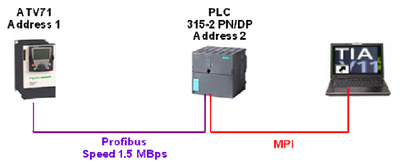
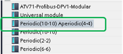
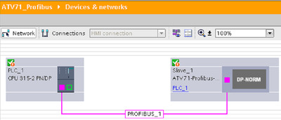
ATV71 on profibus with TIA portal V11.pdf 11/2012 GHD Global Help Desk The goal of this document is to describe the configuration of ATV71 on Profibus with Siemens CPU 315-2 PN/DP with TIA Portal V11. Network Topology used for this example ATV71 configuration PPO cyclic frames contain the periodic variables that are used for 2 types of service:
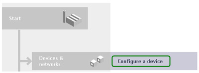
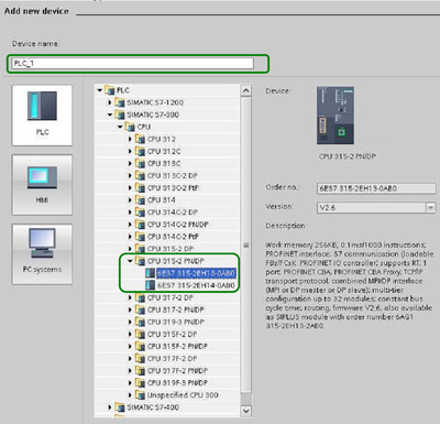
PLC configuration Configure the device Add a new device
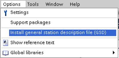
Select the PLC type Add the ATV71 Profibus GSD file Follow the instruction to add the GSD file Profibus DPV0 card (ref : VW3A3307)
Profibus DPV1 card (ref : VW3A3307S371)
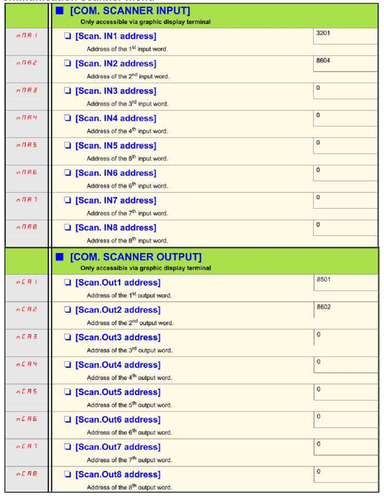
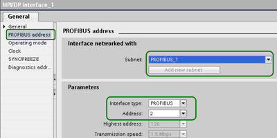
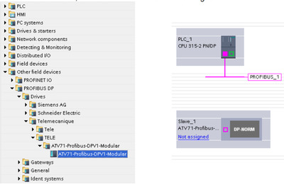
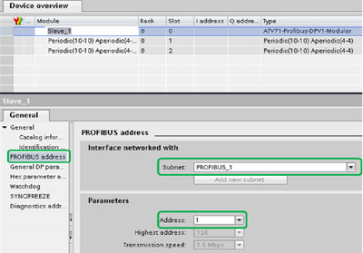
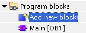
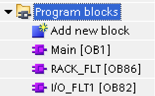
If you don’t use the GSD file in relation with your card reference, the network will not work. Configure the DP port Configure the interface type to Profibus and a add new subnet In network view, add the ATV71 device from catalogue In the ATV71 device view, we select the Telegram to be used We have now the ATV71 and his telegram configured. Inside the ATV71, define the Subnet and the device address (in our case 1) he cyclic exchange have to be configured in the drive (in communication scanner menu) In the network, view assign the PLC1 as master for the ATV71 Click on “Not assigned” in ATV71 and select the PLC interface The ATV71 is now link and the Telegram address Input and output is defined. The I address and O address for the PPO type 5 are define Add OB block to avoid PLC stop in case of rack fault of I/O fault.
We will add OB82 and OB86
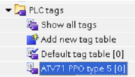
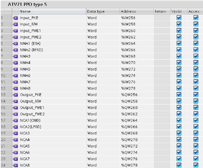
Create PLC tag
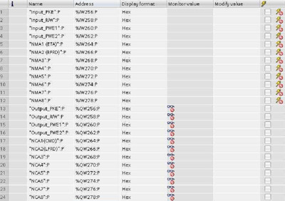
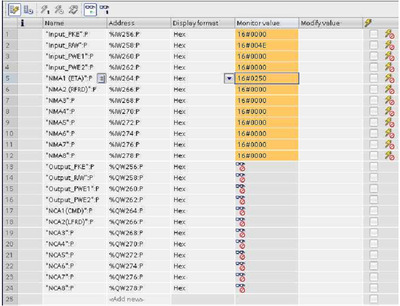
The PPO type 5 input / output began at address 256 The PKW part will be 256 up to 263 and cyclic exchange (NCAx and NMAx) will be 264 up to 282. Even if in this table we have a monitoring mode, it’s does not allow monitoring and using the input and output. To do monitoring and writing of telegram, we have to use the “Watch and Force” table.
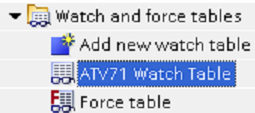
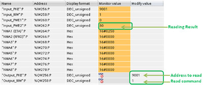
Inside this table we will add the tag define previously but we special syntaxes for using. At this step the configuration is done. We can compile and download the program to the PLC. Monitor and command the ATV71 tart the Drive To send a value, write it and with right click on it, select Modify now. Step 1 The ATV71 status word change Step 2 The ATV71 status word change Step 3 The ATV71 Start. We can monitor the status word and the output speed Using of PKW to read and write drive parameters The following table lists the drive-to-controller parameters in the output PKW area Example to read ACC parameters (address 9001) Example to Write ACC parameters (address 9001) We can check the result We have ATV71 cyclic communication OK. The NCAX and NMAX can be used inside a program. | |
|
| |
| Всего комментариев: 0 | |
