23IOXXX 8-48 Channel RS485 IO Controller Manual
23IOA08_23IOB16_23IOC24_23IOD32_23IOE48 Manual.rar
1. Features:
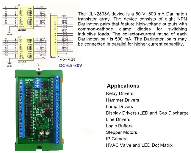
1 Working voltage: DC 6.5-30V (9V 12V 24V)
2 Working current: 8-50MA
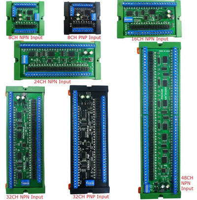
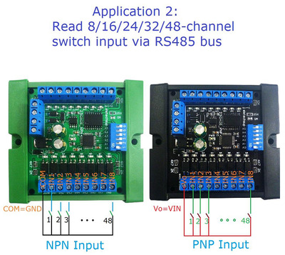
3 8/16/24/32/48 optically isolated input ports, NPN input, 8/32 channel version can choose PNP input
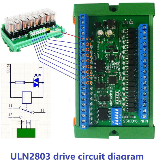
4 8/16/24/32/48 Darlington transistor outputs (ULN2803 NPN output)
5 The default command has a variety of output modes: open, close, jog, self-locking, interlocking, delay six output modes
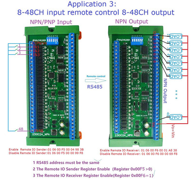
6 The input port can remotely control the output port of another board through the RS485 bus
7 MODBUS command 1 supports 03 06 16 function codes, MODBUS command 2 supports 01/02/03/05/06/15/16 function codes
8 The maximum delay of 1 MODBUS command is 255 seconds
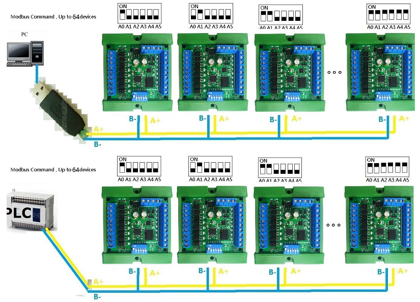
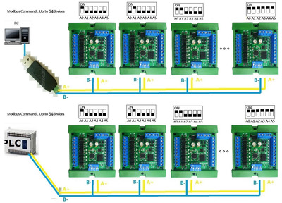
9 In MODBUS command mode, up to 64 devices can be used in parallel
10 The default baud rate is 9600BPS, you can choose the baud rate by jumper: 1200/2400/4800/19200/38400/57600/115200BPS
11 Sizes (with box):
85x80x30mm(8CH),130x80x30mm(16CH),173x80x30mm(24CH),215x80x30mm(32CH),293x80x30mm(48CH)
12 Weight (with box): 97g (8CH), 148g (16CH), 197g (24CH), 246g (32CH), 339g (48CH)
13 Maximum load: the maximum load current of each channel is 300MA
2. Glossary:
Vo: equal to the working voltage DC 6.5-30V
O1/2/3…48: Output ports, low-level output
"Open": the output port outputs low level
"Close": The output port outputs high impedance (floating)
Momentary : Enter the Momentary command, the Rreceiver Relay is Open, delay of 0.5 seconds
after, Relay is Close;
Toggle : Enter the Toggle command, the Rreceiver Relay is Open, Enter the Toggle command
again, Relay is Close;
Latched : Enter the Channel 1 Latched command, the receiver Channel 1 is Open, the Channel 2 is
Close.
Enter the Channel 2 Latched command the receiver Channel 2 is Open, the Channel 1 is Close.
Enter the Channel 3 Latched command the receiver Channel 1 is Close, the Channel 2 is Close.
Delay : Enter the Delay command, the Rreceiver Relay is Open, delay of 0-9999 seconds(MODBUS
command is 0-255 seconds )after, Relay is Close;
During the delay, Eter the Close command, immediately close the relay
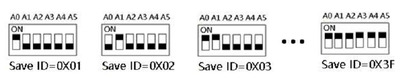
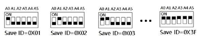
Slave ID: A0-A5 is the slave ID, you can choose 64 different slave ID.
Under the MODBUS command mode,the slave ID must be correct
Command Description:
3 .Output description
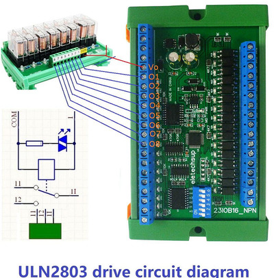

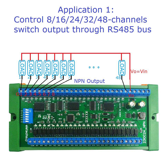
4. Input and output wiring diagram:
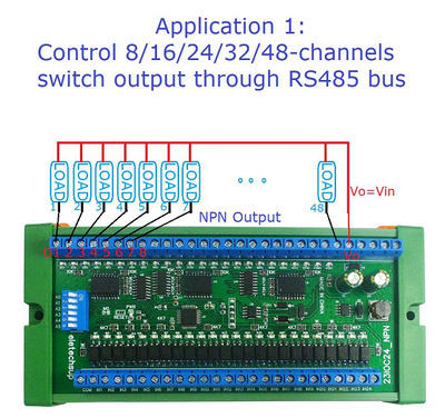
Application 1:
Control 8/16/24/32/48 channel switch output through RS485 bus
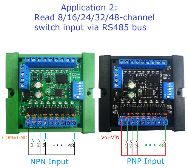
Application 2:
Read 8/16/24/32/48 Channel switch input via RS485 bus
Application 3:
8/16/24/32/48channel input remote control 16-channel output
5 Typical applications:
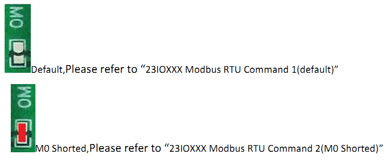
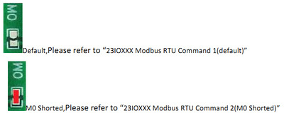
23IOXXX Modbus RTU Command 1
Jumper M0 disconnected (default)
MODBUS command (function code 06/16 is Control command,03 is Read status
command)
Note :
1 MODBUS command must be HEX
2 Slave ID (device address) must be correct, the default slave address is 01, and the Slave ID
is set to see the bottom.
3 If you don't remember the Slave ID, use the command Read Slave ID : FF 03 00 FD 00 01
00 24
The baud rate is 9600 , 8 data bits, one stop bit, and no parity bit.
Product Type
Channles Product Model Product ID Input Type
8 23IOA08 2308 NPN/PNP
16 23IOB16 2316 NPN
24 23IOC24 2324 NPN
32 23IOD32 2332 NPN/PNP
48 23IOE48 2348 NPN
Function code
Function (1) Register
address(2)
Read
number(2)
CRC16(2)
03 Read
06 Write
16(0x10)
Write multiple registersFunction
code
Register address Register
content
Number
of bytes
Register value Remark
03 06
16 (0x10)
0x0000-0x002F
(0-47)
Output port
status
One register for one channel
The following Commands are supported:
Open : 0x0100
Close : 0x0200
Toggle (Self-locking) : 0x0300
Latch(Inter-locking) : 0x0400
Momentary (Non-locking) : 0x0500
Delay : 0x06XX(XX=00-FF) unit: second
Open all : 0x0700
Close all : 0x0800
0X0070-0X0072
(112-114)
Output port
status
One bit for one channel.
Only supports Open and Close Commands.
1 open
0 close
0x0080-0x00AF
(128-175)
Input port
status
One register for one channel
0X0000 no input
0X0001 has input
0X00C0-0X00C2
(192-194)
Input port
status(bit)
One bit for one channel
0 no output
1 has output
Special Function Register:
0X00F5
(245)
Remote IO
Sending
Unit: 0.2 seconds
0 Disable;
1-255 : Send once every 0.2-51 seconds
0X00F6
(246)
Remote IO
Receive
0 Disable;
1 Enable;
0x00F7
(247)
Product ID SKU ID
23IOA08 2308
23IOB16 2316
23IOC24 2324
23IOD32 2332
23IOE48 2348
0x00F8
(248)
Automatic
reporting of
digital
input(DI)
status
0X00C0-0X00C2 register is automatically reported
0: Query function (default)
1-255: Automatically report, the unit is second.
1: Report every 1 second
2: Report every 2 seconds
10: Report every 10 seconds
Maximum interval of 255 seconds0x00FA
(250)
Input and output
relationship ( DI-DO
relationship)
0x0000 Unrelated(default)
0x0001 Self-locking
0x0002 Interlocking (all ch)
0x0003 Momentary
0x0004 Interlocking(2 ch)
0x0005 Output=Input
Other values are the same as 0
0x00FB
(251)
Factory Reset
Enter the following command at the current baud rate:
FF 06 00 FB 00 00 ED E5
0x00FC
(252)
Command
Return Time
2 0-25 data return delay
Return data interval time after receiving
the command (unit 40MS )
0x00FD
(253)
2 RS485 address
(0x01-0x3F)
Products with DIP
switches can only
read
0x00FE
(254)
Baud rate 2 0x0000~0x0007 0:1200
1:2400
2:4800
3:9600 ( default )
4:19200
5:38400
6:57600
7:115200
Others: Factory reset
0x00FF
(255)
Parity 0 None Parity
1 Odd Parity
2 Even Parity
MODBUS 06/16 Command (Control command ,HEX):
Bytes
Number
1 2 3 4 5 6 7 8
MODBUS
Definitions
Slave ID Functio
n
Address Data CRC Check
Function Device
Address
Functio
n
Channel number Comm
and
Delay
time
CRC Check
Open 0x00-0x
F8
0x06
/0x10
0x0000-0x0007 0x01 0x00
2Bytes CRC
Close 0x00-0x
F8
0x06
/0x10
0x0000-0x001F 0x02 0x00
2Bytes CRC
Toggle
(Self-locking)
0x00-0x
F8
0x06
/0x10
0x0000-0x001F 0x03 0x00
2Bytes CRCLatchInter-lo
cking)
0x00-0x
F8
0x06
/0x10
0x0000-0x001F 0x04 0x00
2Bytes CRC
Momentary
(Non-locking
)
0x00-0x
F8
0x06
/0x10
0x0000-0x001F 0x05 0x00
2Bytes CRC
Delay 0x00-0x
F8
0x06
/0x10
0x0000-0x001F 0x06 0x00-0
xff
2Bytes CRC
Open all 0x00-0x
F8
0x06
/0x10
0x0000 0x07 0x00
2Bytes CRC
Close all 0x00-0x
F8
0x06
/0x10
0x0000 0x08 0x00
2Bytes CRC
Remarks:
1 Momentary mode, delay time is 1 seconds
2 Delay mode,delay time is 0-255 seconds
Example:
Examples (Slave ID is 1,DIP switch state)
Channel 1 Open :01 06 00 01 01 00 D9 9A
Channel 1 Close :01 06 00 01 02 00 D9 6A
Channel 1 Toggle:01 06 00 01 03 00 D8 FA
Channel 1 Latch:01 06 00 01 04 00 DA CA
Channel 1 Momentary: 01 06 00 01 05 00 DB 5A
Channel 1 Delay 10 seconds : 01 06 00 01 06 0A 5B AD
Channel 1 Delay 100 seconds: 01 06 00 01 06 64 DA 41
Channel 2 Open :01 06 00 02 01 00 29 9A
Channel 2 Close :01 06 00 02 02 00 29 6A
Channel 2 Toggle :01 06 00 02 03 00 28 FA
Channel 2 Latch :01 06 00 02 04 00 2A CA
Channel 2 Momentary : 01 06 00 02 05 00 2B 5A
Channel 2 Delay 10 seconds : 01 06 00 02 06 0A AB AD
Channel 2 Delay 100 seconds : 01 06 00 02 06 64 2A 41
Open all:01 06 00 00 07 00 8B FA
Close all:01 06 00 00 08 00 8E 0A
16 (0X10) function code
Open Channels1-8:01 10 00 00 00 08 10 01 00 01 00 01 00 01 00 01 00 01 00 01 00 01 00
B4 EB
Close Channels1-4:01 10 00 00 00 04 08 02 00 02 00 02 00 02 00 36 99
Close Channels 5-8:01 10 00 04 00 04 08 02 00 02 00 02 00 02 00 C7 56Output port control (one bit one relay)
Send data
RS485 address
(Station address)
(1)
Functio
n (1)
Register address
(2)
Read number (2) CRC16(2
)
Returns data
RS485 address
(Station address)
(1)
Functio
n (1)
Number of bytes
(1)
data (n) CRC16(2
)
Modbus Address(PLC):40113
RS485 address : 0x01~0Xf8
Function code:Write 0x06/0x16;Read 0x03
Register address: 0x0070-0x0072(112-114) corresponds to the output port
status of channels 0-47
Value : 0 OFF;1 ON
For example 1, Write channel 1/2/3 ON, others OFF:
Send data(address 1): 01 06 00 70 00 07 C9 D3
Return data : 01 06 00 70 00 07 C9 D3
For example 2, Write 16-19 channels ON:
Send data(address 1): 01 06 00 71 FF FF D8 61
Return data : 01 06 00 71 FF FF D8 61Special function Register
1.Set the 485 address(Slave ID)
Send data
Returns data
Modbus Address(PLC):40254
RS485 address :0x01~0Xf8/0XFF
Function code:Write Read 0x03
Register address:0x00FD(253)
Value: 2 bytes (values 1-248)
For example 1: Set the current device address to 0x02
Turn the second bit of the DIP switch to ON, and the other to OFF
For example 2: Read device address,only one RS485 device can be connected
Send data : FF 03 00 FD 00 01 00 24
Return data : 01 03 02 00 01 79 84
Note:With this command, there can be only one module on the bus 485,
More than one will go wrong!
RS485 address
(Station address)
(1)
Functio
n (1)
Register address
(2)
Read number (2) CRC16(2
)
RS485 address
(Station address)
(1)
Functio
n (1)
Number of bytes
(1)
data (n) CRC16(2
)2.Write baud rate
Send data
Returns data
Modbus Address(PLC):40255
RS485 address :0x01~0x3F
Function code:Write 0x06/0x16;Read 0x03
Register address:0x00FE(254)
Value: 2 bytes (values 0-7)
For example 1, Change the baud rate to 4800bps:
Send data(address 1):01 06 00 FE 00 02 69 FB
Return data :01 06 00 FE 00 02 69 FB
Baud rate corresponds to the number: 0:1200 1:2400 2:4800 3:9600
4:19200 5:38400 6:57600 7: 115200 8: Factory reset
Note: 1 The baud rate will be updated only when the module is powered on
again when this command is used!
2 When the number corresponding to the baud rate is 8, the factory
settings can be restored
For example:01 06 00 FE 00 08 E9 FC
For example 2 Read the current baud rate:
Send data(address 1):01 03 00 FE 00 01 E5 FA
Return data :01 03 02 00 03 F8 45
01 RS485 address,03 Function,02 length,F8 45 crc16,03 means the current
baud rate is 9600bps
Baud rate corresponds to the number: 0:1200 1:2400 2:4800 3:9600
4:19200 5:38400 6:57600 7: 115200
RS485 address
(Station address)
(1)
Functio
n (1)
Register address
(2)
Read number (2) CRC16(2
)
RS485 address
(Station address)
(1)
Functio
n (1)
Number of bytes
(1)
data (n) CRC16(2
)3. Set digital input and output relationship (DI-DO relationship):
Send data
Returns data
Modbus Address(PLC):40251
RS485 address :0x01~0x3F
Function code:Write 0x06/0x16;Read 0x03
Register address:0x00FA(250)
Value: 2 bytes (values 0-5)
For example, set the input and output to be unrelated, and change the
register value to 0X0000:
Send data(address 1):01 06 00 FA 00 00 A9 FB
Return data :01 06 00 FA 00 00 A9 FB
Register value:
0x0000 Unrelated(default)
0x0001 Self-locking relationship
0x0002 Interlocking relationship(all channels)
0x0003 Momentary relationship
0x0004 Interlocking relationship(2 channels)
0x0005 Output=Input
Other values are the same as 0x0000
For example: read the current input-output relationship
Send data(address 1):01 03 00 FA 00 01 A4 3B
Return data :01 03 02 00 01 79 84
01 RS485 address,03 Function,02 length 0001is Self-locking relationship
,15 FA crc16
RS485 address
(Station address)
(1)
Functio
n (1)
Register address
(2)
Read number (2) CRC16(2
)
RS485 address
(Station address)
(1)
Functio
n (1)
Number of bytes
(1)
data (n) CRC16(2
)4. Set DI digital input status to automatically report (8/16/24/32/48 channels are
set at the same time):(Automatic reporting of digital input(DI) status)
Send data
Returns data
Modbus Address(PLC):40249
RS485 address :0x01~0x3F
Function code:Write 0x06/0x16;Read 0x03
Register address:0x00F8(248)
Value: 2 bytes (values 0-255)
For example : For example, the current query function should be changed
to automatic reporting:
1 second automatic report : 01 06 00 F8 00 01 C9 FB
2 second automatic report : 01 06 00 F8 00 02 89 FA
3 second automatic report : 01 06 00 F8 00 03 48 3A
4 second automatic report : 01 06 00 F8 00 04 09 F8
5 second automatic report : 01 06 00 F8 00 05 C8 38
10 second automatic report : 01 06 00 F8 00 0A 88 3C
Disable reporting function(Query function): 01 06 00 F8 00 00 08 3B
RS485 address
(Station address)
(1)
Functio
n (1)
Register address
(2)
Read number (2) CRC16(2
)
RS485 address
(Station address)
(1)
Functio
n (1)
Number of bytes
(1)
data (n) CRC16(2
)5. Set Remote IO Sender:
Send data
Returns data
Modbus Address(PLC):40246
RS485 address :0x01~0x3F
Function code:Write 0x06/0x16;Read 0x03
Register address:0x00F5(245)
Value: 2 bytes (values 0-255)
Configure this register, the 23IOXX board will actively send the input
status of IN1-IN8/16/24/32/48 through RS485 Port, and control the output
ports O1-O8/16/24/32/48 of another 23IOXX board (the RS485 address of the
two boards should be the same).
The unit is 0.2 seconds. 0 Disable,1-255 means 0.2-51 seconds to send once
For example, if remote IO sending is currently disable, it should be
changed to allow remote IO sending:
0.2 seconds, send data(RS485 address is 1): 01 06 00 F5 00 01 58 38
0.4 seconds, send frame (address is 1) 01 06 00 F5 00 02 18 39
0.6 seconds, send frame (address is 1) 01 06 00 F5 00 03 D9 F9
0.8 seconds, send frame (address is 1) 01 06 00 F5 00 04 98 3B
1 second, send frame (address is 1) 01 06 00 F5 00 05 59 FB
Disable remote IO sending: send frame (address is 1) 01 06 00 F5 00 00
99 F8
RS485 address
(Station address)
(1)
Functio
n (1)
Register address
(2)
Read number (2) CRC16(2
)
RS485 address
(Station address)
(1)
Functio
n (1)
Number of bytes
(1)
data (n) CRC16(2
)6.Set Remote IO Receive Enable:
Send data
Returns data
Modbus Address(PLC):40247
RS485 address :0x01~0x3F
Function code:Write 0x06/0x16;Read 0x03
Register address:0x00F6(246)
Value: 2 bytes (values 0-255)
When enable Remote IO Sender, please configure this register to 1.
For example,
Enable Remote IO Receive:
send frame (address is 1) 01 06 00 F6 00 01 A8 38
Disable Remote IO Receive:
send frame (address is 1) 01 06 00 F6 00 00 69 F8
Note: When this register is configured as 1, register 0x0080-0x0082 does
not Read
RS485 address
(Station address)
(1)
Functio
n (1)
Register address
(2)
Read number (2) CRC16(2
)
RS485 address
(Station address)
(1)
Functio
n (1)
Number of bytes
(1)
data (n) CRC16(2
)7.Set Command(Date) Return Time
Send data
Returns data
Modbus Address(PLC):40253
RS485 address :0x01~0x3F
Function code:Write 0x06/0x16;Read 0x03
Register address:0x00FC(252)
Value: 2 bytes (values 0-25)
For example, set the data return delay to 200ms
Send data(address 1):01 06 00 FC 00 05 89 F9
Return data :01 06 00 FC 00 05 89 F9
Return the delay time calculation formula:X = 05 * 40 = 200MS
Note: The maximum can be set to 1000MS. If it exceeds 1000MS, that is,
the setting value is greater than 25, and the data return delay will be
initialized.
That is: 01 06 00 FC 00 20 48 22 can make the data return delay to restore
initialization 0
8.Set Parity
Send data
Returns data
Modbus Address(PLC):40256
RS485 address :0x01~0x3F
Function code:Write 0x06/0x16;Read 0x03
Register address:0x00FF(255)
Value: 2 bytes (values 0-2)
RS485 address
(Station address)
(1)
Functio
n (1)
Register address
(2)
Read number (2) CRC16(2
)
RS485 address
(Station address)
(1)
Functio
n (1)
Number of bytes
(1)
data (n) CRC16(2
)
RS485 address
(Station address)
(1)
Functio
n (1)
Register address
(2)
Read number (2) CRC16(2
)
RS485 address
(Station address)
(1)
Functio
n (1)
Number of bytes
(1)
data (n) CRC16(2
)For example, set the parity to Even parity
Send data(address 1):01 06 00 FF 00 01 78 3A
Return data :01 06 00 FF 00 01 78 3A
0 None Parity 1 Even Parity 2 Odd Parity
Note: 1.When using this command, the module is powered on again, and the check
digit will be updated!
2.When the setting is greater than 2, the default value will be restored to 0
after powering on again, and there will be no verification.
9.Factory reset:
Send data
Returns data
Modbus Address(PLC):40252
RS485 address : 0x01~0x3F
Function code:Write 0x06;
Register address:0x00FB(251)
Send data(address 1):FF 06 00 FB 00 00 ED E5
Return data :FF 06 00 FB 00 00 ED E5
Hardware reset: short the RESET/RST jumper of the board for 5
seconds, then power on again.
RS485 address
(Station address)
(1)
Functio
n (1)
Register address
(2)
Read number (2) CRC16(2
)
RS485 address
(Station address)
(1)
Functio
n (1)
Number of bytes
(1)
data (n) CRC16(2
)
23IOXXX Modbus RTU Command 2
Jumper M0 Connected (Soldered)
MODBUS command (function code 05/06/15/16 is Control command,01/02/03 is Read
status command)
M0 jumper must be shorted when using this command
Note :
1 MODBUS command must be HEX
2 Slave ID (device address) must be correct, the default slave address is 01, and the Slave ID
is set by DIP switch.
3 If you don't remember the Slave ID, use the command Read Slave ID : FF 03 00 FD 00 01
00 24
4 M0 jumper must be shorted when using this command
The baud rate is 9600 , 8 data bits, one stop bit, and no parity bit.
Product Type
Channles Product Model Product ID Input Type
8 23IOA08 2308 NPN/PNP
16 23IOB16 2316 NPN
24 23IOC24 2324 NPN
32 23IOD32 2332 NPN/PNP
48 23IOE48 2348 NPNSupported function codes:
Function
Code
Modbus
Address
(PLC)
Register
Address
Describe
01: 00001 0x0000-0x002F
(0-7/15/23/31/47)
Read DO digital output status (relay)
05: 00001 0x0000-0x002F
(0-7/15/23/31/47)
Write a single DO digital output (relay)
15: 00001 0x0000-0x002F
(0-7/15/23/31/47)
Write multiple DO digital output (relay)
02: 10001 0x0000-0x002F
(0-7/15/23/31/47)
Read DI digital input (optical isolation input)
03 40001
0x0080-0x00FF
(128-255)
Read special function registers (baud rate 485
address, etc.)
06 40001
0x0080-0x00FF
(128-255)
Write a single special function register (baud
rate 485 address, etc.)
16(0x10) 40001
0x0080-0x00FF
(128-255)
Write multiple special function registers (baud
rate 485 address, etc.)
All states are mapped into 4xxxx range registers. The user can monitor the input and output
status of the module by reading or modifying the value of the 4xxxx interval register (03 06
16 function code)
Register
address
Register contents Register
value
Remarks R/W
0x0080-0X0082
(128-130)
DO digital output 0X0080: 0-15 Channels
0X0081: 16-31 Channels
0X0082: 32-47 Channels
One bit one channel
only supports ON/OFF Command:
1 ON; 0 OFF
R/W
0x0090-0x0092
(144-146)
DI digital input 0X0090: 0-15 Channels
0X0091: 16-31 Channels
0X0092: 32-47 Channels
1 has Input; 0 has no Input
RSpecial Function Register:
0X00F5
(245)
Remote IO Sending Unit: 0.2 seconds
0 Disable;
1-255 : Send once every 0.2-51 seconds
R/W
0X00F6
(246)
Remote IO Receive 0 Disable;
1 Enable;
R/W
0x00F7
(247)
Product ID SKU ID
23IOA08 2308
23IOB16 2316
23IOC24 2324
23IOD32 2332
23IOE48 2348
R/W
0x00F8
(248)
Automatic reporting
of digital input(DI)
status
0X00C0-0X00C2 register is automatically
reported
0: Query function (default)
1-255: Automatically report, the unit is
second.
1: Report every 1 second
2: Report every 2 seconds
10: Report every 10 seconds
Maximum interval of 255 seconds
R/W
0x00FA
(250)
Input and output
relationship(DI-DO
relationship)
0x0000 Unrelated(default)
0x0001 Self-locking
0x0002 Interlocking(all ch)
0x0003 Momentary
0x0004 Interlocking(2 ch)
0x0005 Output=Input
Other values are the same as 0
R/W
0x00FB
(251)
Factory Reset
Enter the following command at the current baud rate:
FF 06 00 FB 00 00 ED E5
R/W
0x00FC
(252)
Command Return
Time
0-25 Time interval for command
return (unit: 40MS) Setting
value: 0-25
R/W
0x00FD
(253)
RS485 address
(Station address)
Products with DIP switches can only read
Read address:FF 03 00 FD 00 01 00 24;
R
0x00FE
(254)
Baud rate 0-7 0:1200
1:2400
2:4800
3:9600(default)
4:19200
5:38400
6:57600
7:115200
R/WOthers:Factory reset
0x00FF
(255)
Parity 0-2 0 None Parity
1 Even Parity
2 Odd Parity
R/W
9600 Band ,8 Data bits,None Parity,1 Stop Bit。
MODBUS commands you can use "Modbus Poll" input, as shown below
(CRC check generated automatically)
You can also use HyperTerminal serial input, as shown below
(Manually add CRC check)1. Read DI digital input status (NPN/PNP photoelectric isolation
input): Send data
Returns data
Modbus Address(PLC):10001-10008
RS485 address : 0x01~0x3F
Function code: 0x02
Register address:0x0000-0x0007
Read number :0x0001-0x0008
For example, read the status of DI digital input of channel 0-7:
Send data(address 1): 01 02 00 00 00 08 79 CC
Return data : 01 02 01 89 60 2E
01 RS485 address, 02 function code, 01 length, 89 refers to the current
DI digital input status, converted to binary 10001001, indicating that
0/3/7 channels have input, and other channels have no input.
In addition, the DI digital input is also mapped to the 40000 interval
register. The user can read the value of the DI digital input through
the 03 function code.
Modbus Address(PLC):40145
RS485 address : 0x01~0x3F
Function code:0x03
Register address:0x0090
Read number: 0x0001
For example, read the status of DI digital input of channel 0-7:
Send data(address 1): 01 03 00 90 00 01 84 27
Return data : 01 03 02 00 56 38 7A
01 RS485 address, 03 function code, 02 length, 0056 refers to the
current DI digital input status, converted to binary 01010110,
indicating that 1/2/4/6 channels have input, and other channels have
no input.
RS485 address
(Station address)
(1)
Functio
n (1)
Register address
(2)
Read number (2) CRC16(2
)
RS485 address
(Station address)
(1)
Functio
n (1)
Number of bytes
(1)
data (n) CRC16(2
)2.Read DO digital output status :
Send data
Returns data
Modbus Address(PLC):00001-00008
RS485 address : 0x01~0x3F
Function code: 0x01
Register address:0x0000-0x0007
Read number :0x0001-0x0008
For example, read the status of DO digital output of channel 0-7:
Send data(address 1): 01 01 00 00 00 08 3D CC
Return data : 01 01 01 B8 51 FA
01 RS485 address, 01 function code, 01 length, B8 refers to the current
DO digital output status, converted to binary 10111000, indicating
that 7/5/4/3 channels have output, and other channels have no output.
In addition, the DO digital output is also mapped to the 40000
interval register. The user can read the value of the DO digital output
through the 03 function code.
Modbus Address(PLC):40129
RS485 address : 0x01~0x3F
Function code:0x03
Register address:0x0080
Read number: 0x0001
For example, read the status of DO digital output of channel 0-7:
Send data(address 1): 01 03 00 80 00 01 85 E2
Return data : 01 03 02 00 38 B9 96
01 RS485 address, 03 function code, 02 length, 0038 refers to the
current DO digital output status, converted to binary 00111000,
indicating that 3/4/5 channels have output, and other channels no
output.
RS485 address
(Station address)
(1)
Functio
n (1)
Register address
(2)
Read number (2) CRC16(2
)
RS485 address
(Station address)
(1)
Functio
n (1)
Number of bytes
(1)
data (n) CRC16(2
)3. Write single DO digital output status :
Send data
Returns data
Modbus Address(PLC):00001-00008
RS485 address : 0x01~0x3F
Function code:0x05
Register address:0x0000-0x0007
For example 1, Write channel 0 to ON, others OFF:
Send data(address 1):01 05 00 00 FF 00 8C 3A
Return data :01 05 00 00 FF 00 8C 3A
For example 2, Write channel 5 to ON, others OFF:
Send data(address 1):01 05 00 05 FF 00 9C 3B
Return data :01 05 00 05 FF 00 9C 3B
For example 3, Write channel 7 to ON, others OFF:
Send data(address 1):01 05 00 07 FF 00 7C 0B
Return data :01 05 00 07 FF 00 7C 0B
In addition, the DO digital output is also mapped to the 40000 interval
register. The user can write the DO digital output value through the
06/16 function code.
Modbus Address(PLC):40129
RS485 address :0x01~0x3F
Function code:0x06/0x10
Register address:0x0080
For example, Write channel 0/3 to ON, others OFF:
Send data(address 1):01 06 00 80 00 09 48 24
Return data :01 06 00 80 00 09 48 24
RS485 address
(Station address)
(1)
Functio
n (1)
Register address
(2)
Read number (2) CRC16(2
)
RS485 address
(Station address)
(1)
Functio
n (1)
Number of bytes
(1)
data (n) CRC16(2
)4.Write multiple DO digital output status (relay output):
Send data
Returns data
Modbus Address(PLC):00001-00008
RS485 address :0x01~0x3F
Function code:0x0F
Register address:0x0000-0x0007
For example 1, Write channel 0-7 to OFF:
Send data(address 1):01 0F 00 00 00 08 01 00 FE 95
Return data :01 0F 00 00 00 08 54 0D
For example 1, Write channel 0-7 to ON:
Send data(address 1):01 0F 00 00 00 08 01 FF BE D5
Return data :01 0F 00 00 00 08 54 0D
For example 3, Write channel 0/1/3/7 to ON, others OFF:
Send data(address 1):01 0F 00 00 00 08 01 8B BE F2
Return data :01 0F 00 00 00 08 54 0D
In addition, the DO digital output is also mapped to the 40000 interval
register. The user can write the DO digital output value through the
06/16 function code.
Modbus Address(PLC):40129
RS485 address :0x01~0x3F
Function code:0x06/0x10
Register address:0x0080
For example, Write channel 0/3 to ON, others OFF:
Send data(address 1):01 06 00 80 00 09 48 24
Return data :01 06 00 80 00 09 48 24
RS485 address
(Station address)
(1)
Functio
n (1)
Register address
(2)
Read number (2) CRC16(2
)
RS485 address
(Station address)
(1)
Functio
n (1)
Number of bytes
(1)
data (n) CRC16(2
)Special function Register
1.Set the 485 address(Slave ID)
Send data
Returns data
Modbus Address(PLC):40254
RS485 address :0x01~0Xf8/0XFF
Function code:Write Read 0x03
Register address:0x00FD(253)
Value: 2 bytes (values 1-248)
For example 1: Set the current device address to 0x02
Turn the second bit of the DIP switch to ON, and the other to OFF
For example 2: Read device address,only one RS485 device can be connected
Send data : FF 03 00 FD 00 01 00 24
Return data : 01 03 02 00 01 79 84
Note:With this command, there can be only one module on the bus 485,
More than one will go wrong!
2.Write baud rate
Send data
Returns data
RS485 address
(Station address)
(1)
Functio
n (1)
Register address
(2)
Read number (2) CRC16(2
)
RS485 address
(Station address)
(1)
Functio
n (1)
Number of bytes
(1)
data (n) CRC16(2
)
RS485 address
(Station address)
(1)
Functio
n (1)
Register address
(2)
Read number (2) CRC16(2
)
RS485 address
(Station address)
(1)
Functio
n (1)
Number of bytes
(1)
data (n) CRC16(2
)Modbus Address(PLC):40255
RS485 address :0x01~0x3F
Function code:Write 0x06/0x16;Read 0x03
Register address:0x00FE(254)
Value: 2 bytes (values 0-7)
For example 1, Change the baud rate to 4800bps:
Send data(address 1):01 06 00 FE 00 02 69 FB
Return data :01 06 00 FE 00 02 69 FB
Baud rate corresponds to the number: 0:1200 1:2400 2:4800 3:9600
4:19200 5:38400 6:57600 7: 115200 8: Factory reset
Note: 1 The baud rate will be updated only when the module is powered on
again when this command is used!
2 When the number corresponding to the baud rate is 8, the factory
settings can be restored
For example:01 06 00 FE 00 08 E9 FC
For example 2 Read the current baud rate:
Send data(address 1):01 03 00 FE 00 01 E5 FA
Return data :01 03 02 00 03 F8 45
01 RS485 address,03 Function,02 length,F8 45 crc16,03 means the current
baud rate is 9600bps
Baud rate corresponds to the number: 0:1200 1:2400 2:4800 3:9600
4:19200 5:38400 6:57600 7: 115200
3. Set digital input and output relationship (DI-DO relationship):
Send data
Returns data
Modbus Address(PLC):40251
RS485 address :0x01~0x3F
Function code:Write 0x06/0x16;Read 0x03
RS485 address
(Station address)
(1)
Functio
n (1)
Register address
(2)
Read number (2) CRC16(2
)
RS485 address
(Station address)
(1)
Functio
n (1)
Number of bytes
(1)
data (n) CRC16(2
)Register address:0x00FA(250)
Value: 2 bytes (values 0-5)
For example, set the input and output to be unrelated, and change the
register value to 0X0000:
Send data(address 1):01 06 00 FA 00 00 A9 FB
Return data :01 06 00 FA 00 00 A9 FB
Register value:
0x0000 Unrelated(default)
0x0001 Self-locking relationship
0x0002 Interlocking relationship(all channels)
0x0003 Momentary relationship
0x0004 Interlocking relationship(2 channels)
0x0005 Output=Input
Other values are the same as 0x0000
For example: read the current input-output relationship
Send data(address 1):01 03 00 FA 00 01 A4 3B
Return data :01 03 02 00 01 79 84
01 RS485 address,03 Function,02 length 0001is Self-locking relationship
,15 FA crc16
4. Set DI digital input status to automatically report (8/16/24/32/48 channels are
set at the same time):(Automatic reporting of digital input(DI) status)
Send data
Returns data
Modbus Address(PLC):40249
RS485 address :0x01~0x3F
Function code:Write 0x06/0x16;Read 0x03
Register address:0x00F8(248)
Value: 2 bytes (values 0-255)
RS485 address
(Station address)
(1)
Functio
n (1)
Register address
(2)
Read number (2) CRC16(2
)
RS485 address
(Station address)
(1)
Functio
n (1)
Number of bytes
(1)
data (n) CRC16(2
)For example : For example, the current query function should be changed
to automatic reporting:
1 second automatic report : 01 06 00 F8 00 01 C9 FB
2 second automatic report : 01 06 00 F8 00 02 89 FA
3 second automatic report : 01 06 00 F8 00 03 48 3A
4 second automatic report : 01 06 00 F8 00 04 09 F8
5 second automatic report : 01 06 00 F8 00 05 C8 38
10 second automatic report : 01 06 00 F8 00 0A 88 3C
Disable reporting function(Query function): 01 06 00 F8 00 00 08 3B
5. Set Remote IO Sender:
Send data
Returns data
Modbus Address(PLC):40246
RS485 address :0x01~0x3F
Function code:Write 0x06/0x16;Read 0x03
Register address:0x00F5(245)
Value: 2 bytes (values 0-255)
Configure this register, the 23IOXX board will actively send the input
status of IN1-IN8/16/24/32/48 through RS485 Port, and control the output
ports O1-O8/16/24/32/48 of another 23IOXX board (the RS485 address of the
two boards should be the same).
The unit is 0.2 seconds. 0 Disable,1-255 means 0.2-51 seconds to send once
For example, if remote IO sending is currently disable, it should be
changed to allow remote IO sending:
0.2 seconds, send data(RS485 address is 1): 01 06 00 F5 00 01 58 38
0.4 seconds, send frame (address is 1) 01 06 00 F5 00 02 18 39
RS485 address
(Station address)
(1)
Functio
n (1)
Register address
(2)
Read number (2) CRC16(2
)
RS485 address
(Station address)
(1)
Functio
n (1)
Number of bytes
(1)
data (n) CRC16(2
)0.6 seconds, send frame (address is 1) 01 06 00 F5 00 03 D9 F9
0.8 seconds, send frame (address is 1) 01 06 00 F5 00 04 98 3B
1 second, send frame (address is 1) 01 06 00 F5 00 05 59 FB
Disable remote IO sending: send frame (address is 1) 01 06 00 F5 00 00
99 F8
6.Set Remote IO Receive Enable:
Send data
Returns data
Modbus Address(PLC):40247
RS485 address :0x01~0x3F
Function code:Write 0x06/0x16;Read 0x03
Register address:0x00F6(246)
Value: 2 bytes (values 0-255)
When enable Remote IO Sender, please configure this register to 1.
For example,
Enable Remote IO Receive:
send frame (address is 1) 01 06 00 F6 00 01 A8 38
Disable Remote IO Receive:
send frame (address is 1) 01 06 00 F6 00 00 69 F8
Note: When this register is configured as 1, register 0x0080-0x0082 does
not Read
7.Set Command(Date) Return Time
Send data
Returns data
RS485 address
(Station address)
(1)
Functio
n (1)
Register address
(2)
Read number (2) CRC16(2
)
RS485 address
(Station address)
(1)
Functio
n (1)
Number of bytes
(1)
data (n) CRC16(2
)
RS485 address
(Station address)
(1)
Functio
n (1)
Register address
(2)
Read number (2) CRC16(2
)
RS485 address
(Station address)
Functio
n (1)
Number of bytes
(1)
data (n) CRC16(2
)Modbus Address(PLC):40253
RS485 address :0x01~0x3F
Function code:Write 0x06/0x16;Read 0x03
Register address:0x00FC(252)
Value: 2 bytes (values 0-25)
For example, set the data return delay to 200ms
Send data(address 1):01 06 00 FC 00 05 89 F9
Return data :01 06 00 FC 00 05 89 F9
Return the delay time calculation formula:X = 05 * 40 = 200MS
Note: The maximum can be set to 1000MS. If it exceeds 1000MS, that is,
the setting value is greater than 25, and the data return delay will be
initialized.
That is: 01 06 00 FC 00 20 48 22 can make the data return delay to restore
initialization 0
8.Set Parity
Send data
Returns data
Modbus Address(PLC):40256
RS485 address :0x01~0x3F
Function code:Write 0x06/0x16;Read 0x03
Register address:0x00FF(255)
Value: 2 bytes (values 0-2)
For example, set the parity to Even parity
Send data(address 1):01 06 00 FF 00 01 78 3A
Return data :01 06 00 FF 00 01 78 3A
0 None Parity 1 Even Parity 2 Odd Parity
Note: 1.When using this command, the module is powered on again, and the check
digit will be updated!
2.When the setting is greater than 2, the default value will be restored to 0
after powering on again, and there will be no verification.
(1)
RS485 address
(Station address)
(1)
Functio
n (1)
Register address
(2)
Read number (2) CRC16(2
)
RS485 address
(Station address)
(1)
Functio
n (1)
Number of bytes
(1)
data (n) CRC16(2
)9.Factory reset:
Send data
Returns data
Modbus Address(PLC):40252
RS485 address : 0x01~0x3F
Function code:Write 0x06;
Register address:0x00FB(251)
Send data(address 1):FF 06 00 FB 00 00 ED E5
Return data :FF 06 00 FB 00 00 ED E5
Hardware reset: short the RESET/RST jumper of the board for 5
seconds, then power on again.
RS485 address
(Station address)
(1)
Functio
n (1)
Register address
(2)
Read number (2) CRC16(2
)
RS485 address
(Station address)
(1)
Functio
n (1)
Number of bytes
(1)
data (n) CRC16(2
) |